![]()
Power FC FD Igniter Installation
An FD Igniter is necessary when installing an FD APEXi Power
FC into an FC3s
 |
 |
|
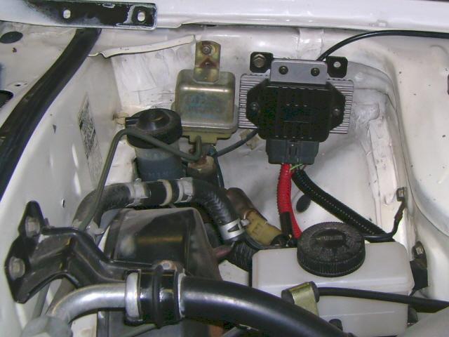
Pic #1 (FD Igniter)
|
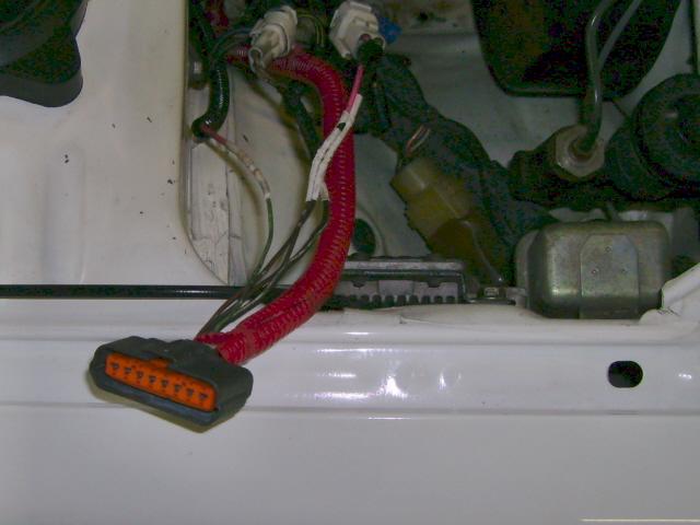
Pic #2 (FD Igniter Connector)
|
FC Coil Photographs
 |
 |
 |
|
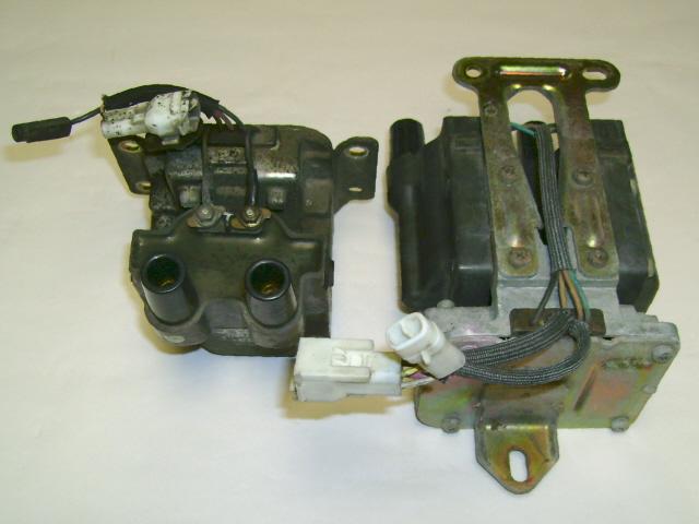
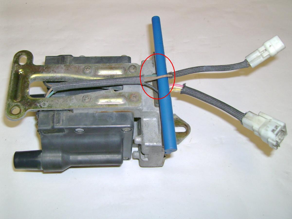
Pic #3 (FC Coils)
|
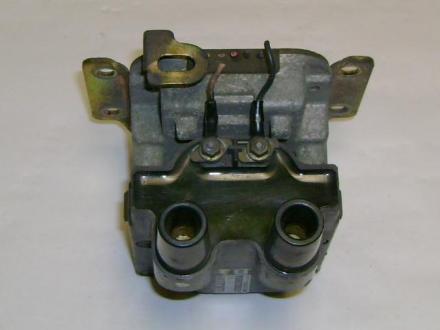
Pic #4 (Igniter Wires Removed)
|
Pic #5 (Trailing Coil Tan Wire)
|
Tools Required:
- Wire Strippers
- Wire Cutter
- Soldering Iron & Solder
- 10mm Socket/Ratchet
Parts Required:
- FD Igniter & Connector
- 12 Gauge Wire Shielded
- Heat-Shrink Tubing
- 10mm Bolts
Procedure
The FD Power FC lacks the switching wire, which allows the trailing coils to switch from T1 to T2. Installation of the FD Igniter will allow the ignition system to operate correctly. This procedure details the process of completely bypassing the FC igniters while maintaining the use of the ignition coils. Ensure that you use heat shrink tubing on all soldering connections.
1. Start by finding a suitable location to mount the FD Igniter, preferably close to the coils. The igniter grounds to the chassis, so it must be securely fastened. NOTE: we installed FD Coils under the UIM on our 13B-RE project and were able to mount the FD Igniter in the trailing coil location.
2. Remove Leading & Trailing Coils from the vehicle (Pic #3)
3. Cut ALL wires leading to and from the igniters (Pic #4); NOTE: DO NOT cut the tan wire that goes directly to the positive terminal on the T2 Coil (Pic #5). You will have a 2-pin connector with one pink wire and one tan wire for the leading coil. The trailing coil will have a 4-pin connector with yellow, grey, white and pink wires, along with a 2-pin connector with two tan wires, one of which you did not cut.
4. Solder the yellow and grey wires together on the 4-pin trailing coil connector. This will supply the Tach Signal.
5. Solder the tan wire coming from the positive terminal on the T1 Coil to the tan wire coming from the positive terminal on the T2 coil (the one that you did not cut), leaving one tan wire available on the 2-pin trailing coil connector.
6. Solder the tan wire on the 2-pin leading coil connector to the tan wire on the positive terminal of the leading Coil.
The next part of the procedure tackles installation of the wiring for the FD Igniter.
Ensure that you have sufficient amount of wire to reach the coils from wherever the igniter is mounted. Use shielded wire from the igniter to the coils.
 |
|
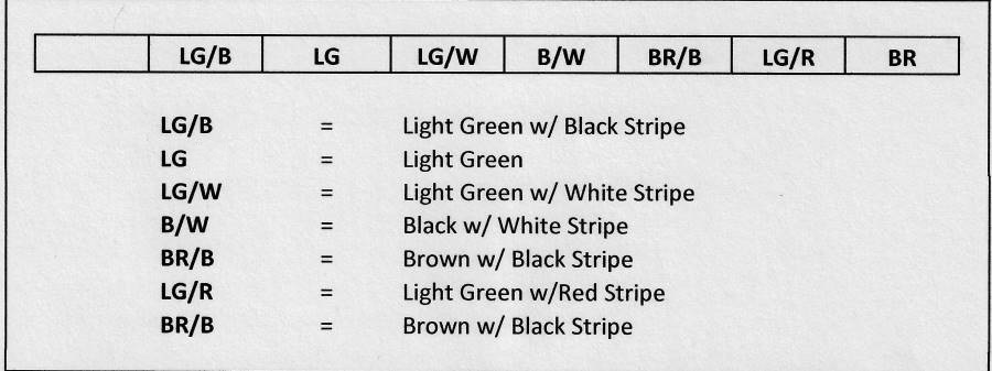
Igniter Connector
|
7.
Solder the light green w/ black stripe
wire from the igniter to the black wire on the negative terminal of the leading
coil.
8.
Solder the light green wire from the
igniter to the pink wire on the 2-pin leading coil connector.
9.
Solder the light green w/ white stripe
wire from the igniter to the blue wire going to the negative post on the T2
Coil.
10. Solder the black w/ white stripe
wire from the igniter to the unused tan wire coming from the 2-pin trailing
coil connector.
11.
Solder the brown w/ black stripe wire
from the igniter to the white wire on the 4-pin trailing coil connector.
12.
Solder the light green w/ red stripe
wire from the igniter to the black wire going to the negative post on the
T1 coil.
13.
Solder the brown wire from the igniter
to the pink wire on the 4-pin trailing coil connector.
This concludes the soldering and wiring portion of the procedure.
14. Reinstall coils into factory locations.
15. Plug connectors back into factory harness.
Click Here for PDF version
Banzai Racing is not responsible for any adverse effects due to this or any modification
Contact
Us if you have any questions about this How To
Click Home button to visit Banzai Racing's Website if necessary